
What Is an Optical Splitter? Working Principle, Types, and Applications
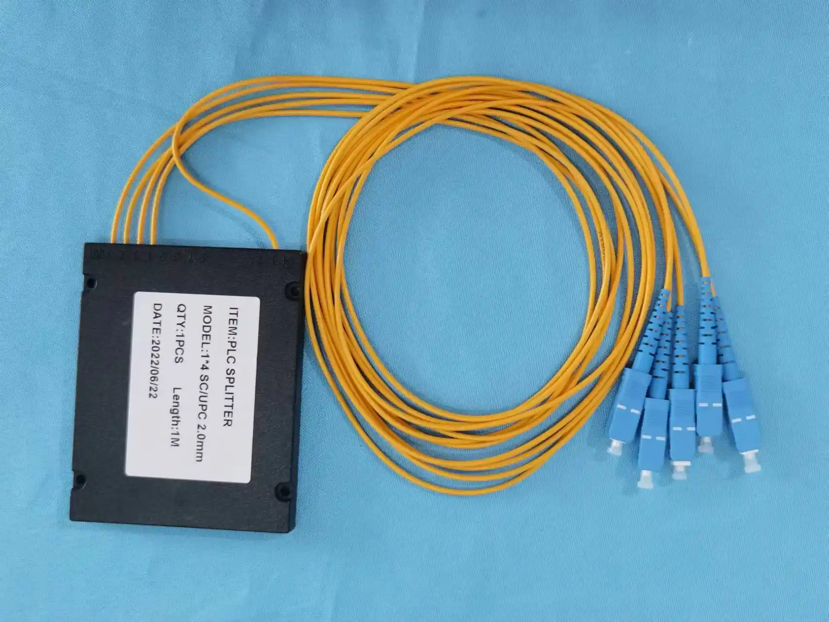
The optical splitter is a passive fiber optics device that splits a single optical signal into two or more signals, allowing several users or devices to use one fiber. The optical splitter is widely used in fiber-to-the-home (FTTH) networks, passive optical networks (PON), and other fiber optics communications.
Optical splitter allows distributing optical signals without using any external power source. It helps to reduce expenses on network infrastructure and make fiber distribution easier. The optical splitter is an integral part of modern optical access networks.
What Is an Optical Splitter?
The optical splitter or the fiber optic splitter or optical power splitter is a passive optical device intended for splitting light signals from one input port to several output ports.
For example, a 1×8 optical splitter accepts one input signal and splits it into eight output signals. Each of the output signals has a certain portion of the original optical power and enables several subscribers to get information via optical distribution network.
Unlike other active optical equipment, an optical splitter does not require any power supply, electronic signal processing, or amplification. The optical splitter splits optical power in itself but maintains the transmission of optical signals.
Optical splitters are widely used in:
- fiber distribution boxes
- fiber optic distribution frames (ODF)
- optical distribution networks (ODN)
- FTTH access networks
- outdoor telecom cabinets
- central offices and data communication centers
Principle of Operation of Optical Splitter
In an optical splitter, incoming light gets divided into several outputs. This process depends on the internal structure of the splitter and its manufacturing technology.
In a PON, the OLT transmits downstream signals via the feeder fiber. Further, the optical power is delivered to the passive optical splitter, where it is distributed among several ONTs/ONUs.
This process can be explained in three steps as follows:
- Inputting the optical signal: the splitter gets the optical signal via the input port.
- Distributing the optical power: the internal optical structure of the splitter divides the incoming light into several channels.
- Outputting the optical signal: each output port emits a part of the optical power into the subscriber or network endpoint.
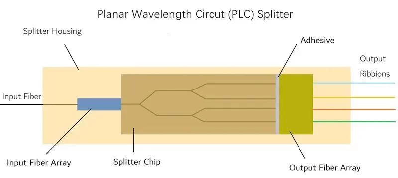
The distribution of optical power depends on the splitting ratio. Some common splitting ratios are 1×2, 1×4, 1×8, 1×16, 1×32, 1×64.
An ideally working 1×8 splitter should have the equal optical power in each output that will be equal to one-eighth of the original optical power. But, due to optical losses such as insertion losses, the actual optical power in each output will be less than the theoretical value.
This is why it is necessary to consider the loss of the splitter while designing a fiber optic network.
Types of Optical Splitters
There are two basic types of optical splitters which differ from each other in manufacturing techniques. They are PLC optical splitters and FBT optical splitters.
PLC Optical Splitter
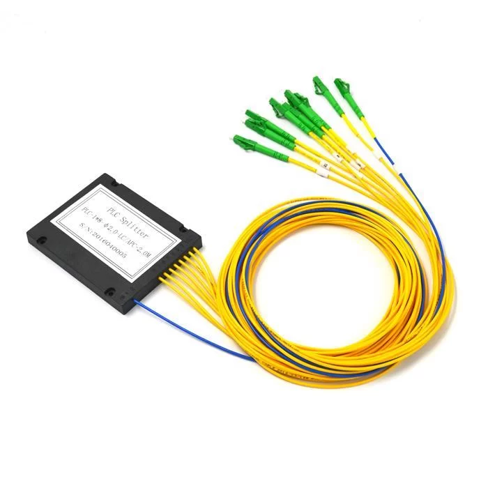
A PLC (Planar Lightwave Circuit) splitter is an optical device that consists of silica-based optical chip with integrated waveguides. It splits the optical signals and is widely used in modern FTTH and PON networks due to its relatively uniform power distribution.
The main features of PLC splitters are as follows:
- High splitting ratios (1×8, 1×16, 1×32, 1×64);
- Relatively uniform insertion loss across all output ports;
- Operating wavelength range flexibility;
- Small dimensions, suitable for high density installation;
- Effective usage in large-scale fiber distribution networks.
PLC optical splitters are usually preferable in case of using multiple output ports and stable optical performance.
FBT Optical Splitter
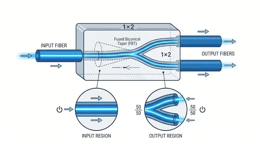
An FBT (Fused Biconical Taper) splitter is created by heating, stretching and fusing together two or more optical fibers. This way, a coupling area is created where optical power is transferred between optical fibers.
In comparison with PLC splitters, FBT splitters are more advantageous in applications which require fewer output ports or special power distribution.
Features of FBT optical splitters include:
- Low manufacturing cost for some low port configurations;
- Availability in symmetrical and asymmetrical splitting ratios;
- Applicability in 1×2 and 1×4 configurations;
- Designing for some specific wavelengths;
- Usage for signal monitoring and optical power tapping.
PLC vs. FBT Optical Splitters
| Feature | PLC Splitter | FBT Splitter |
| Manufacturing technology | Planar waveguide circuit | Fused fiber taper |
| Common configurations | 1×2 to 1×64 | Mainly low-port configurations |
| Power distribution | Generally uniform | Uniform or unequal |
| Wavelength performance | Broadband | More wavelength-dependent |
| Typical applications | FTTH, GPON, EPON | Monitoring and low-ratio splitting |
Both technologies have their own advantages. The correct selection of a splitter depends on network design, splitting requirements, operating wavelengths and budget of the project.
Common Split Ratios for Optical Splitters
The split ratio indicates how many output ports could have the incoming optical signal.
Typical combinations include:
- 1×2: one input signal splits into two output signals.
- 1×4: one input signal feeds four output signals.
- 1×8: one input signal connects to eight output signals.
- 1×16: sixteen output signals could be provided.
- 1×32: optical power divides into thirty-two endpoints.
- 1×64: up to sixty-four output signals could be supported.
The higher splitting ratio allows a greater number of users to use the same feeder fiber, but it causes additional optical power loss.
For an ideal equal splitter, the theoretical splitting loss will be:
Splitting Loss (dB) = 10 × log₁₀(N)
Here, N represents the number of output ports.
| Split Ratio | Ideal Splitting Loss |
| 1×2 | 3.01 dB |
| 1×4 | 6.02 dB |
| 1×8 | 9.03 dB |
| 1×16 | 12.04 dB |
| 1×32 | 15.05 dB |
| 1×64 | 18.06 dB |
When designing the PON network, engineers should calculate the total optical power budget that includes splitter loss, fiber loss, connector loss, and splice loss.
Applications of Optical Splitters
The optical splitter is an essential device used in the fiber optic communication system due to its feature of signal distribution without using any electrical power source. As such, optical splitters can be deployed in various kinds of networks.
1. FTTH Networks
FTTH technology uses optical splitters to broadcast the signals from central office to many subscriber homes. The operators benefit from this technology by reducing feeder fibers and making last mile connections easier.
2. PON Networks
GPON and EPON networks use passive optical splitters to build a point to multipoint connection between the OLT and multiple ONUs or ONTs.
3. Telecom Distribution Network
The optical splitters are used inside outdoor distribution cabinets, fiber distribution boxes, and splice closures to connect fibers in different parts of the network.
4. Business Network
The optical splitters can be deployed in business establishments including campus and enterprise networks in order to distribute the signals to multiple buildings or network terminals.
5. Fiber Monitoring Systems
The asymmetric splitters can be used to tap some fraction of the optical power for monitoring purposes.
How to Choose the Suitable Optical Splitter
When choosing an appropriate optical splitter, it’s vital to take into account certain technical characteristics to keep the performance level and reliability of the network.
- Splitting ratio: It’s necessary to define the number of output ports based on the number of subscribers or network nodes.
- Insertion loss: It’s important to determine the maximum insertion loss in order to fit it into the optical power budget.
- Operating wavelength: Make sure that the splitter is compatible with the wavelengths being used in the communication system.
- Connector type: The most popular types include SC/APC, SC/UPC, LC/APC, and LC/UPC.
- Installation environment: You need to choose between indoor distribution box, outdoor cabinet, splice closure, or rack-mounted ODF.
- Operating temperature: In case of the outdoor use, you need to consider the environmental conditions of the installation place.
- Output uniformity: You need to pay attention to the difference in optical power of output ports.
In the process of designing the network, it’s better not to select a device with the maximum splitting ratio. 1×64 splitter will connect more subscribers than 1×16 splitter, but at the same time, it will have more insertion loss. This can limit the transmission distance and reduce the optical power budget.
Huijue Group Optical Splitter Solutions
With the rapid growth of fiber optics networks, reliable optical distribution parts become necessary for constructing an efficient communication network.
The range of Huijue Group's fiber optic products includes optical splitters and other fiber optic components used in the telecommunication and network distribution applications. The solutions of our products involve splitting ratio and installation formats for FTTH, FTTx, and passive optical networks.
In choosing an optical splitter, we suggest assessing the entire network structure instead of assessing only the component itself. An appropriate combination of splitting ratio, insertion loss, connectors, and installation formats will guarantee stable signal distribution and effective work of the network.
For both new FTTH deployment and fiber network expansion, it is possible to choose adequate optical distribution parts to increase the efficiency of network infrastructure utilization and its further development.
Conclusion
Optical splitter is an essential passive component in fiber optic communication networks. It separates one input optical signal into several outputs in order to enable point-to-multipoint distribution in fiber optics without any need of power supply.
Knowledge about its working mechanism, technologies, splitting ratio, and performance parameters will allow project managers to choose the right optical splitters for their projects. When proper optical power budgeting is done, it can be used in FTTH/PON networks successfully.